
 We are pleased to announce that Principled Technologies has acquired Demartek.

Demartek Storage Networking Interface Comparison
Updated 26 August 2019
The Demartek Storage Interface Comparison reference page provides information on interfaces used in computer storage devices including Ethernet, Fibre Channel, FCoE, InfiniBand, iSCSI, NVMe, PCI Express, SAS, SATA, Thunderbolt and USB. This material includes history and roadmaps, comments on data transfer rates, cabling and connectors and more. The goal is to provide IT professionals with a great deal of useful data center infrastructure information in one place.
Special Announcement — SD cards to use NVMe
September 2018 - We have added a new SD Express area in the roadmap section of this document.
We started this reference page in 2010 and update it periodically as we discover new information. As you might imagine, this page has grown over time.
Most of the interface types listed here are known as “block” interfaces, meaning that they provide an interface for “block” reads and writes. They simply provide a conduit for blocks of data to be read and written, without regard to file systems, file names or any other knowledge of the data in the blocks. The host requesting the block access provides a starting address and number of blocks to read or write.
We have produced deployment guides for some of the technologies described in this document.
- Demartek Fibre Channel Deployment Guide
- Demartek iSCSI Deployment Guide
- Demartek RoCE Deployment Guide (Updated July 2018)
- Demartek SSD Deployment Guide
Also see our Storage Tutorial Videos.
Contents
- Acronyms
- Storage Networking Interface Comparison Table
- Transfer Rate, Bits vs. Bytes, and Encoding Schemes
- History
- Roadmaps
- Cables: Fiber Optics and Copper
- Connector Types
- PCI Express® (PCIe®)
Acronyms
- FC — Fibre Channel (also see Demartek FC Zone)
- FCoE — Fibre Channel over Ethernet (also see Demartek FCoE Zone)
- IB — InfiniBand
- iSCSI — Internet Small Computer System Interface (also see Demartek iSCSI Zone)
- NVMe — NVM Express (also see Demartek NVMe Zone)
- PCIe — PCI Express
- SAS — Serial Attached SCSI
- SATA — Serial ATA
- USB — Universal Serial Bus
- 10GbE — 10 Gigabit Ethernet
- CNA — Converged Network Adapter (used with FCoE)
- HBA — Host Bus Adapter (used with FC, iSCSI, SAS, SATA)
- HCA — Host Channel Adapter (used with IB)
- NIC — Network Interface Controller or Network Interface Card (used with FCoE, iSCSI)
- ISL — Inter-Switch Link
- SAN — Storage Area Network
- Gb — Gigabit
- GB — Gigabyte
- Mb — Megabit
- MB — Megabyte
- Tb — Terabit
- TB — Terabyte
- Gb/s — Gigabits per second
- Gbit/s — Gigabits per second
- Gbps — Gigabits per second
- GB/s — Gigabytes per second
- GBps — Gigabytes per second
- Mb/s — Megabits per second
- Mbit/s — Megabits per second
- Mbps — Megabits per second
- MB/s — Megabytes per second
- MBps — Megabytes per second
- Tb/s — Terabits per second
- Tbit/s — Terabits per second
- Tbps — Terabits per second
- TB/s — Terabytes per second
- TBps — Terabytes per second
- HDD — Hard Disk Drive
- SSD — Solid State Drive (also see Demartek SSD Zone)
- SSHD — Solid State Hybrid Drive
- SDR — Single Data Rate (InfiniBand)
- DDR — Double Data Rate (InfiniBand)
- QDR — Quad Data Rate (InfiniBand)
- FDR — Fourteen Data Rate (InfiniBand)
- EDR — Enhanced Data Rate (InfiniBand)
- HDR — High Data Rate (InfiniBand)
| Number of Devices | Maximum Distance (m) | Cable Type | Interface Device | Transfer Rate (MB/sec) | Interface Attributes | |
|---|---|---|---|---|---|---|
| FC | 16M | 10 (copper) 10KM+ (optical) |
Copper Optical |
HBA | 100, 200, 400, 800, 1600, 3200 | Dual Port |
| FCoE | 16M | 10 (copper) very long (optical) |
Copper Optical |
CNA 10GbE NIC |
1150, 4600 | Dual Port |
| IB | 48M | 15 (copper) very long (optical) |
Copper Optical |
HCA | 1000, 2000, 4000, 7000, 12,500 | full-duplex, Dual Port |
| iSCSI | Many | Ethernet cable distance | Copper Optical |
NIC, HBA | 100, 1000, 4000 | |
| SAS (passive) |
16K | 10 | Copper | Onboard, HBA | 300, 600, 1200 | full-duplex, Dual Port |
| SAS (active) |
16K | 20 | Copper | Onboard, HBA | 300, 600, 1200 | full-duplex, Dual Port |
| SAS (active) |
16K | 100 | Optical | Onboard, HBA | 300, 600, 1200 | full-duplex, Dual Port |
| SATA | 1 | 1 | Copper | Onboard, HBA | 150, 300, 600 | half-duplex, Single Port |
| Thunderbolt | 6 | 4 | Copper | Onboard | 1000, 2000, 4000 | |
| USB | 127 | 5 | Copper, Wireless | Onboard, Adapter card | 0.15, 1.5, 48, 500, 1000 | Single Port |
PCIe data rates are provided in the PCI Express section below.
Transfer Rate
Transfer rate, sometimes known as transfer speed, is the maximum rate at which data can be transferred across the interface. This is not to be confused with the transfer rate of individual devices that may be connected to this interface. Some interfaces may not be able to transfer data at the maximum possible transfer rate due to processing overhead inherent with that interface or the protocol used on that interface. Some interface adapters provide hardware offload functions to improve performance, manageability and/or reliability of the data transmission across the respective interface. The transfer rates listed are across a single port at half-duplex (from point A to point B, one direction at a time).
Bits vs. Bytes and Encoding Schemes
Transfer rates for storage interfaces and devices are generally listed as MB/sec or MBps (MegaBytes per second),
which is generally calculated as Megabits per second (Mbps) divided by 10. Many of these interfaces use
“8b/10b” encoding which maps 8 bit bytes into 10 bit symbols for transmission on the wire, with the extra
bits used for command and control purposes. When converting from bits to bytes on the interface, dividing
by ten (10) is exactly correct. 8b/10b encoding results in a 20 percent overhead (10-8)/10 on the raw bit rate.
Beginning in 2010 newer encoding schemes emerged that improve data transfer efficiency. The first of these newer encoding schemes is known as “64b/66b” and is used for 10GbE, 10GbFC (for ISL’s) and 16Gb FC and some of the higher data rates for IB. 64b/66b encoding is not directly compatible with 8b/10b, but the technologies that implement it are built so that they can work with the older encoding scheme. 16Gb Fibre Channel uses a line rate of 14.025 Gbps, but with the 64b/66b encoding scheme results in a doubling of the throughput of 8Gb Fibre Channel, which uses a line rate of 8.5 Gbps with the 8b/10b encoding scheme. 64b/66b encoding results in a 3 percent overhead (66-64)/66 on the raw bit rate.
PCIe versions 1.x and 2.x use 8b/10b encoding. PCIe version 3 uses 128b/130b encoding, resulting in a 1.5 percent overhead on the raw bit rate. Additional PCIe information is provided in the PCI Express section below.
USB 3.1 Gen 2 (10 Gbps) uses use 128b/132b encoding. See Roadmaps section below.
| Overhead | Applications | |
|---|---|---|
| 8b/10b | 20% | 1GbE, FC (up to 8Gb), IB (SDR, DDR & QDR), PCIe (1.0 & 2.0) SAS, SATA, USB (up to 3.0) |
| 64b/66b | 3% | 10GbE, 100GbE, FC (10Gb, 16Gb & 32Gb), FCoE, IB (FDR & EDR), Thunderbolt 2 |
| 128b/130b | 1.5% | PCIe 3.0, 24G SAS (likely) |
| 128b/132b | 3% | USB 3.1 Gen 2 (10 Gbps, see Roadmaps section below) |
| Throughput* (MBps) | Line Rate (GBaud) | Encoding | Host Adapter requirements (dual-port cards) |
|
|---|---|---|---|---|
| 1GFC | 100 | 1.0625 | 8b/10b | PCI-X |
| 2GFC | 200 | 2.125 | 8b/10b | PCI-X |
| 4GFC | 400 | 4.25 | 8b/10b | PCI-X 2.0 or PCIe 1.0 x4 |
| 8GFC | 800 | 8.5 | 8b/10b | PCIe 1.0 x8 or PCIe 2.0 x4 |
| 16GFC | 1600 | 14.025 | 64b/66b | PCIe 2.0 x8 or PCIe 3.0 x4 |
| 32GFC | 3200 | 28.05 | 64b/66b | PCIe 3.0 x8 |
Fibre Channel speeds are often abbreviated into the form nnGFC, indicating nn Gbps Fibre Channel.
| 1X data rate * | 4X data rate * | 12X data rate * | Encoding | Host Adapter requirements (dual-port cards) |
|
|---|---|---|---|---|---|
| SDR | 2 Gb/s | 8 Gb/s | 24 Gb/s | 8b/10b | PCIe 1.0 x8 |
| DDR | 4 Gb/s | 16 Gb/s | 48 Gb/s | 8b/10b | PCIe 1.0 x16 or PCIe 2.0 x8 |
| QDR | 8 Gb/s | 32 Gb/s | 96 Gb/s | 8b/10b | PCIe 2.0 x8 |
| FDR-10* * Mellanox only |
10.3125 Gb/s | 41.25 Gb/s | 123.75 Gb/s | 64b/66b | PCIe 3.0 x8 |
| FDR | 13.64 Gb/s | 54.55 Gb/s | 163.64 Gb/s | 64b/66b | PCIe 3.0 x8 |
| EDR | 25 Gb/s | 100 Gb/s | 300 Gb/s | 64b/66b | PCIe 3.0 x16 |
InfiniBand connections can be aggregated into 4x (4 lanes) and 12x (12 lanes), depending on the application and connector. QSFP and QSFP+ connectors are used for 4x connections, and CXP connectors are typically used for 12x connections. See the Connector Types section below for more details on the connector types. Newer IB speeds have been announced that are described in the Roadmaps section below.
History
Products became available with the interface speeds listed during these years. Newer interface speeds are often
available in switches and adapters long before they are available in storage devices and storage systems.
All the interface speeds listed are single direction, or half-duplex mode (from point A to point B). Some of
these interfaces can also operate in bi-directional or full-duplex mode (both directions simultaneously).
For bi-directional rates, double the data rates.
- FC — 1 Gb/s in 1997, 2 Gb/s in 2001, 4 Gb/s in 2005, 8 Gb/s in 2008, 10 Gb/s (ISL only) 2004, 16 Gb/s in 2011, 32 Gb/s in 2016 (FC is generally backward compatible with the previous two generations)
- FCoE — FC: 4 Gb/s and Ethernet: 10 Gb/s in 2008, 10 Gb/s in 2009.
(FC-BB-5 was approved in June 2009, INCITS 462-2010 was approved in Spring 2010) - IB — 10 Gb/s in 2002, 20 Gb/s in 2005, 40 Gb/s in 2008, 56 Gb/s in 2011, 100 Gb/s in 2015.
- iSCSI — 1 Gb/s in 2003, 10 Gb/s in 2007 (basic 10GbE first appeared in 2002)
- NVMe — Version 1.0 specification published in March 2011. Version 1.1 specification finalized in October 2012. Version 1.2 specification released in November 2014. Version 1.3 specification released in June 2017. Version 1.4 specification released in July 2019. NVMe over Fabrics 1.0 specification released in June 2016. As of August 2019, the NVMe over Fabrics 1.1 specification was in its 45-day review period.
- SAS — 3 Gb/s in 2005, 6 Gb/s in 2009, 12 Gb/s in 2H 2013
- SCSI Express — SCSI Express was an effort to place the SCSI protocol over the PCI Express interface and included SCSI over PCIe (SOP) and PCIe queueing interface (PQI). SCSI Express was first submitted as a proposal in 2011 and accepted as a formal project in 2012, but was de-emphasized during 2015. Although the SCSI Express specification was completed in 2013, as of mid-2016 there was little or no industry adoption, work on SCSI Express development had stopped and no SCSI Express products became available.
- SATA — 1.5 Gb/s in 2003, 3 Gb/s in 2005, 6 Gb/s in 2010 (traditional SATA is not expected to extend beyond 6 Gb/s, see Roadmaps section below)
- SATA μSSD was introduced in August 2011 as a new implementation of SATA for embedded SSDs. These devices do not have the traditional SATA interface connector but use a single ball grid array (BGA) package that can be surface mounted directly on a system motherboard. These SATA μSSD devices are intended for mobile platforms such as tablets and ultrabooks, and consume less electric power than traditional SATA interface devices.
- SATA Revision 3.2 was ratified and announced in August 2013. This revision included new SATA form factors, details for SATA Express, power management enhancements and optimizations for solid state hybrid drives (SSHDs). One of the new SATA form factors was M.2 that enables small form-factor SATA SSDs suitable for thin devices such as tablets and notebooks. M.2 was formerly known as NGFF, is defined by the PCI-SIG and supports a variety of applications including WiFi, WWAN, USB, PCIe and SATA. The v3.2 specification standardizes the SATA M.2 connector pin layout. SATA v3.2 also introduced USM Slim, which reduced the thickness of the module from 14.5mm to 9mm.
- SATA Express — SATA Express was included in SATA Revision 3.2. SATA Express was an attempt to combine traditional SATA with the PCI Express interface. However, SATA Express did not gain market acceptance and development on it has ceased.
- SATA Revision 3.3 was published in February 2016. This revision of the SATA specification introduced support for shingled magnetic recording (SMR) for hard disk drives and some technical enhancements relating to remote power cycling of SATA drives, staggered spin-up and more.
- SATA Revision 3.4 was published in June 2018. This revision of the SATA specification introduced new management and monitoring features including device temperature monitoring, durable/ordered write notification (writing selected data from cache to the media) and device sleep signal timing.
- Thunderbolt — 10 Gb/s in 2011, 20 Gb/s in late 2013, 40 Gb/s in 2015
- USB — 1.5 Mb/s in 1997, 12 Mb/s in 1999, 480 Mb/s in 2001, 5 Gb/s in 2009, 10 Gb/s specification completed in 2014
PCIe history is provided in the PCI Express section below.
Roadmaps
These roadmaps include the estimated calendar years that higher speeds may become available and are based on our industry
research, which are subject to change. Past history indicates that several of these interfaces are on a three to five
year development cycle for the next improvement in speed. It is reasonable to expect that pace to continue.
It usually takes several months after the specification is complete before products are generally available in the marketplace.
Typically, test equipment becomes available before end-user products become available. Widespread adoption of those new
products takes additional time, sometimes years.
Some of the standards groups are now working on “Energy Efficient” versions of these interfaces to indicate additions to
their respective standards to reduce power consumption.
All the interface speeds listed are single direction, or half-duplex mode (from point A to point B). Some of
these interfaces can also operate in bi-directional or full-duplex mode (both directions simultaneously).
For bi-directional rates, double the data rates.
See the Connector Types section below for additional roadmap information.
Roadmap slides are courtesy of the respective industry organizations.
- Ethernet
Ethernet Roadmap

- Roadmap — In 2019 the Ethernet Alliance updated its public roadmap for new speeds of Ethernet. Now that single-lane 25GbE products are generally available, the development efforts are now focused on higher single-lane speeds and several multi-lane specifications, including duo, quad and eight-lane configurations. All of these new speeds and configurations have obvious implications for storage applications for block protocols as well as file and object storage protocols. The Connector Types section below has additional information on single-lane and multi-lane connection technology.
- 2.5GBASE-T and 5GBASE-T — In September 2016, the IEEE-SA Standards Board approved IEEE Std 802.3bz-2016. It defines 2.5GbE using Cat 5e cable up to 100 m and 5GbE using Cat 6 cable up to 100 m. Components such as controllers, connector modules and transceivers, as well as end-user products such as switches and adapters that support this standard, also known as “Multi-gigabit” Ethernet, are beginning to appear in 2017. Some of the early products are 10GbE products that have added 2.5GbE and 5GbE support, but these have higher power requirements and prices. Some of the newer products are expected to support 1GbE, 2.5GbE and 5GbE without 10GbE support and will probably have lower power requirements and lower price points.
- Fibre Channel (FC)
Fibre Channel Roadmap

- 64GFC — In November 2018, the Fibre Channel Industry Association (FCIA) announced the completion of PC-PI-7 specification, also known as 64GFC. Some 64GFC products are available as of 2019 but shipped with 32GFC optics (transceivers). We expect 64GFC optics to become available in volume in 2020. The T11 standards group split out the 256GFC (4 x 64) parallel portion of the specification into FC-PI-7P, expecting it to reach letter ballot by the middle of 2019. The underlying technology used for single-lane 64GFC is based on the same fundamental circuitry as the single-lane 50Gb Ethernet specification, but single-lane 64GFC runs at a different baud rate. In addition, 64GFC has a much more stringent bit error rate (BER) requirement and higher loss budget than Ethernet in order to operate in a lossless manner. 64GFC products support the PCIe 4.0 technology. As usual, each FC revision will be backwards compatible with at least the two previous generations.
- 128GFC — Development work began in 2018 for the 128GFC standard, known as FC-PI-8. The underlying technology used for single-lane 128GFC is based on the same fundamental circuitry as the single-lane 100Gb Ethernet specification, but single-lane 128GFC runs at a different baud rate. In addition, 128GFC has a much more stringent bit error rate (BER) requirement and higher loss budget than Ethernet in order to operate in a lossless manner. The T11 standards group expects to complete the 128GFC specification in calendar year 2020 or 2021. Each FC revision will be backwards compatible with at least the two previous generations.
- SAN interface — FC has a future as a SAN interface for the foreseeable future. There has been a huge investment (US$ Billions) in FC infrastructure over the years, primarily in enterprise datacenters, which is likely to remain deployed for many years. According to various industry analysts, Fibre Channel continues to be the most popular host interface for external storage systems. Some newer storage vendors that did not originally include FC as a host interface have plans to add it.
- Disk drive interface — FC has reached end-of-life as a disk drive interface, as the disk drive and SSD manufacturers have largely moved to SAS and NVMe as the primary device interfaces for enterprise drives.
- FC-NVMe — The FC-NVMe standard is a combination of the NVMe-oF standard from the NVM Express group and the Fibre Channel standard from the T11 group. Both specifications are complete. The FC-NVMe standard was published by the International Committee on Information Technology Standards (INCITS) in June 2018. Development of drivers to support FC-NVMe in existing FC host adapters for various operating environments is well underway. Fibre Channel host adapters (initiator and target) support traditional Fibre Channel protocol (FCP) and FC-NVMe protocol simultaneously. Fibre Channel switches require no changes to support FC-NVMe. Adapter, switch and storage system products that support FC-NVMe are expected to appear in the market in 2018.
- FC-NVMe-2 — The T11 organization started a new FC-NVMe-2 standard in early 2018. FC-NVMe-2 introduces sequence level error recovery into the NVMe-oF standard as implemented in Fibre Channel. This overcomes the disconnect behavior that NVMe-oF performs when certain errors occur. Fibre Channel recovery methods will be used to prevent disconnects and handle these errors gracefully. The FC-NVMe-2 standard became feature complete by the end of calendar year 2018. The first Letter Ballot for approval started in early 2019.
- FCoE
- FCoE is becoming a “first hop” technology used primarily in blade servers to communicate with internal blade switches. Typically, these blade switches communicate either with Ethernet or Fibre Channel external switches and fabrics. There is no separate roadmap for FCoE, as it uses existing Ethernet speeds.
- InfiniBand (IB)

- HDR (High Data Rate) 200 Gb/s (4 x 50 Gb/s) — HDR IB is expected to become available in 2H 2017. 200 Gb/s adapters will require either PCIe 3.0 x32 (in two adjacent x16 slots) or PCIe 4.0 x16 slots in the servers to support adapters running at the full data rate.
- HDR Copper Cables — Copper cables are expected to be supported at HDR (200 Gb/s), for distances up to at least 3 meters (50 Gb/s per lane).
- Beyond HDR — NDR and XDR have been announced and are on the roadmap. NDR is estimated to become available in 2020, but no date for XDR has been published. The general expectation is that each of these will probably double the data rate of the previous data rate.
- NDR — Next Data Rate is expected after HDR.
- XDR — eXtreme Data Rate is expected after NDR.
- iSCSI
- Speeds follow Ethernet roadmap.
- iSER — iSCSI Extensions for RDMA (Remote Direct Memory Access – allows data bypass the TCP/IP stack, cutting down on data copies and CPU utilization. iWARP(Internet Wide Area RDMA Protocol) and RoCE (RDMA over Converged Ethernet) are the two protocols enabling RDMA for Ethernet in rNICs (RDMA Network Interface Controllers).
- NVMe

- NVMe 2.0 — Development is underway on NVMe 2.0. This next version combines the base NVMe specification and the NVMe over Fabrics (NVMe-oF) specification into a single specification going forward, with completion of the NVMe 2.0 specification targeted for 2020 or 2021. Also see FC-NVMe and FC-NVMe-2 in the Fibre Channel area of this roadmap section above.
- NVMe-MI 1.1 — NVMe Management Interface (NVMe-MI) specification, version 1.1, was published in April 2019. This version includes enclosure management, among other things.
- SAS

- 24G SAS specifications — As of June 2017, development is complete (functionally complete) on the 24G SAS specification, comprised of SAS-4 and SPL-4 by the INCITS T10 committee and products are being developed. 24G SAS is backward compatible with 12 Gb/s and 6 Gb/s SAS but will use a different encoding scheme than previous versions. See the Demartek report discussing Applications Driving 24G SAS for additional detail on the 24G SAS specifications.
- 24G SAS products — Prototype 24G SAS products were on display at the Flash Memory Summit (FMS) in August 2019. 24G SAS products will be a compliment to PCIe Gen4 platforms. See the PCI Express section below for information on PCIe 4.0.
- SAS Advanced Connectivity — New SAS cabling options are offering longer distances by using active copper (powered signal) and optical cables. The Mini SAS HD connector can be used for 6 Gb/s SAS and 12 Gb/s SAS connections. See the connector types section below for discussion of Mini SAS and Mini SAS HD connectors. For both 12 Gb/s SAS and 24G SAS, external passive copper cables are expected to support up to 6 meters, active copper up to 20 meters and optical cables at least 100 meters. Internal cables are expected to support 1 meter for speeds up to 24G SAS. SAS Device to Mid-plane interconnects are expected to support 1-port, 2-port and 4-port connections (up to 4 x 24G) at half-duplex.
- 24G SAS connector types — Two new connector types for 24G SAS are expected to become available, in addition to the existing Mini SAS HD. These are OCuLink and SlimLine. These provide options for smaller connectors and different cabling.
- SAS Advanced Features — SAS has a flexible structure, allowing enhancements to be added to the protocol and higher layers that are separate from the speed increases. SAS Storage Intelligence (SSD optimizations) and persistent connections are two features that were added to 12 Gb/s SAS after the 12 Gb/s SAS specification was completed. This flexibility will allow other new features to be added to 24G SAS in the future.
- SATA
- SATA New Features — New features are expected to be added to the SATA specification periodically as needed. The pattern in the past has seen new revisions of the SATA specification every year or two. See the history section above for the various revisions to the SATA specification.
- SD7.0 with SD Express and SD Ultra Capacity
- The SD Express 7.0 specification, announced in June 2018, adds the popular PCI Express® and NVMe™ interfaces to the legacy SD interface. This new specification for the well-known SD cards used in consumer devices is will support speeds up to 985 MB/sec of throughput, far higher than previous SD specifications. With this new speed and interface, a variety of applications, including consumer, IoT and enterprise, will be able to run directly on SD Express media.
- SD Ultra Capacity (SDUC) extends the potential maximum capacity of SD cards to 128TB from the previous limit of 2TB.
- The SD7.1 specification, announced in February 2019, adds the microSD Express card that incorporates the SD Express interface using PCIe NVMe to the microSD form factor.
- SD Express 7.0 will support PCIe gen 3 and NVMe v1.3. It uses the second row of pins also used by the UHS-II interface and therefore will not support the UHS-II interface. Development work is already underway to support PCIe gen 4, possibly in a specification to be announced in 2019.
- SMB/NFS
- Speeds follow Ethernet roadmap.
- NFS v1 (Network File System) — filesharing protocol developed in 1984 by Sun.
- SMB (Server Message Block) 1.0 — Formerly known as CIFS (Common Internet File System), it is a filesharing protocol developed in 1990.
- NFS v2, v3, v4 v4.1 — Improved NFS protocol releases, with the last release in 2010.
- SMB 2.0 — New version of SMB that reduced chattiness, released in 2006.
- SMB 3.0 — New version of SMB that supports multichannel, transparent failover, and SMB Direct. The SMB Direct protocol uses SMB protocol with RDMA (Remote Direct Memory Access). iWARP and RoCE are the two protocols enabling RDMA for ethernet.
- SMB 3.1.1 — Released in 2016. Adds security/encryption features.
- Thunderbolt

- Thunderbolt 3 (40 Gb/s) — Thunderbolt 3 was announced in June 2015. Thunderbolt 3 supports speeds up to 40 Gb/s with active copper or optical cables, or 20 Gb/s with passive copper cables. Thunderbolt 3 supports up to four lanes of PCI Express 3.0.
-
USB
- USB data rates — The USB 3.0 Promoter Group announced at the end of July 2013 that the USB 3.1 specification had been completed. USB 3.1 enables USB to operate at 10 Gbps, and is backward compatible with existing USB 3.0 and 2.0 hubs and devices. USB 3.1 uses a 128b/132b encoding scheme, with four bits used for command and control for the protocol and the cable management. The first public prototype demonstration of USB running at 10 Gbps was made in September 2013. USB 3.1 is expected to support USB Power Delivery (described below). In the summer of 2015, the USB-IF renamed the 5 Gbps and 10 Gbps USB speeds to SuperSpeed USB (USB 3.1 Gen 1, 5 Gbps) and SuperSpeed USB 10 Gbps (USB 3.1 Gen 2).
- USB Power Delivery — USB is becoming a power delivery interface, with an increasing number of devices charging or receiving power via USB ports in computers or wall sockets and power strips. The USB Power Delivery (PD) Specification, version 1.0, was introduced in July 2012 to allow an increased amount of power to be carried via USB. This specification proposes to raise the limit from 7.5 watts up to 100 watts of power, depending on cable and connector types. Devices negotiate with each other to determine voltage and current levels for the power transmission, and power can flow in either direction. Devices can adjust their power charging rates while transmitting data. Prototypes began to appear in late 2013.
- USB Type-C Cable — The specification for the new Type-C USB cable and connector was completed in August 2014. This USB cable has an entirely new design with a smaller connector size that can be easily used with a variety of types of devices. With this new specification, the connector and cable are reversible with respect to the plug orientation and the direction of the cable. Type-C USB cables will have the same type of connector on each end of the cable, so it will not matter which end of the cable is plugged into a computer, hub, charger or other device. The Type-C USB cables are electronically marked so that cable information can be passed to the device. Initial cable lengths will be up to 1m in length and use passive copper technology. Active copper and optical cables could be produced in the future. The USB Type-C cable is also used in Thunderbolt 3 applications (see Thunderbolt above) that supports USB, Thunderbolt and DisplayPort protocols.
- In March 2019, the USB Promoter Group announced the pending release of the USB 4 (“USB4”) specification. USB4 will support up to 40 Gbps speed by using two-lane cables, will be compatible with Thunderbolt devices, and will allocate bandwidth between video and data traffic.
SAS-SATA Connector Compatibility

Source: SCSI Trade Association
Express Bay Connector Backplane

Source: SCSI Trade Association
Cables: Fiber Optics and Copper
As interface speeds increase, expect increased usage of fiber optic cables and connectors for most interfaces. At higher Gigabit speeds (10Gb+), copper cables and interconnects generally have too much amplitude loss except for short distances, such as within a rack or to a nearby rack. This amplitude loss is sometimes called a poor signal-to-noise ratio or simply “too noisy”.
Fiber-optic cables: Single-mode fiber vs. Multi-mode fiber
There are two general types of fiber optic cables available: single-mode fiber and multi-mode fiber.
- Single-mode fiber (SMF), typically with an optical core of approximately 9 µm (microns), has lower modal dispersion than multi-mode fiber and can support distances up to 80-100 Km (Kilometers) or more, depending on transmission speed, transceivers and the buffer credits allocated in the switches.
- Multi-mode fiber (MMF), with optical core of either 50 µm or 62.5 µm, supports distances up to 600 meters, depending on transmission speeds and transceivers.
When planning datacenter cabling requirements, be sure to consider that a service life of 15 to 20 years can be expected for fiber optic cabling, so the choices made today need to support legacy, current and emerging data rates. Also note that deploying large amounts of new cable in a datacenter can be labor-intensive, especially in existing environments.
There are different designations for fiber optic cables depending on the bandwidth supported.
- Multi-mode: OM1, OM2, OM3, OM4, OM5 (OM1 and OM2 are considered “legacy” products)
- Single-mode: OS1a is for indoor use, OS2 is for outdoor use.
OM3 and OM4 are multi-mode cables that are “laser optimized” (LOMMF) and support 10 Gigabit per lane and faster applications (Ethernet, Fibre Channel, etc.). For Ethernet, this includes 10GbE and 25GbE technologies. For higher speeds, multiple lanes are bundled together (4 x 10Gbps, 4 x 25Gbps, etc.). See the Connector Types section below for additional detail.
Newer multi-mode OM2, OM3 and OM4 (50 µm) and single-mode OS1 (9 µm) fiber optic cables have been introduced that can handle tight corners and turns. These are known as “bend optimized,” “bend insensitive,” or have “enhanced bend performance.” These fiber optic cables can have a very small turn or bend radius with minimal signal loss or “bending loss.” The term “bend optimized” multi-mode fiber (BOMMF) is sometimes used.
OM5 fiber-optic cable, known as wideband multi-mode fiber (WBMMF), transmits four wavelengths (colors) simultaneously using short wavelength division multiplexing (SWDM) to achieve 100Gbps (4 x 25Gbps) transmission on a single-lane connection. OM5 carries at least four times more capacity than OM4 over the same distance. When configured in four parallel lanes (four sets of fiber), transmission speed can reach 400Gbps.
OS1a and OS2 single-mode fiber optics are used for long distances, up to 10,000m (6.2 miles) with the standard transceivers and have been known to work at much longer distances with special transceivers and switching infrastructure. OS1a replaces OS1, as OS1 is considered a “legacy” product.
Each of the multi-mode and single-mode fiber optic cable types includes two wavelengths. The higher wavelengths are used for longer-distance connections. OM5 supports more than two wavelengths.
Update: 24 April 2012 — The Telecommunications Industry Association (TIA) Engineering Committee TR-42 Telecommunications Cabling Systems has approved the publication of TIA-942-A, the revised Telecommunications Infrastructure Standard for Data Centers. A number of changes were made to update the specification with respect to higher transmission speeds, energy efficiency and harmonizing with international standards. For backbone and horizontal cabling and connectors, the following are some of the important updates:
- Copper cabling — Cat 6 is the minimum requirement, Cat 6a recommended
- Fiber optic cabling — OM3 is the minimum requirement, OM4 is recommended
- Fiber optic connectors — LC is the standard for one or two fiber connectors
Update: June 2017 — The TIA approved for publication the TIA-942-B data center cabling standard at its June 2017 meeting. This standard includes several updates from Revision-A including:
- Addendum 1 for data center fabrics
- 16- and 32-fiber MPO-style connectors
- Category 8 twisted pair cable, expected to support 25GBASE-T and 40GBASE-T applications
- A new OM5 fiber-optic cable type (wideband multimode fiber or WBMMF) that supports short-wave wavelength division multiplexing (see TIA-492-AAAE)
Ethernet Fiber-Optic Cables
- 10GBASE-SR — Currently, the most common type of fiber-optic 10GbE cable is the 10GBASE-SR cable that supports an SFP+ connector with an optical transceiver rated for 10Gb transmission speed. These are also known as 10GbE “short reach” fiber-optic cables, typically within a datacenter.
- 10GBASE-LR — These are the 10GbE “long reach” fiber optic cables that support single-mode fiber optic cables and connectors up to 10 KM.
- 10GBASE-ER — These are the 10GbE “extended reach” fiber optic cables that support single-mode fiber optic cables and connectors up to 40 KM.
- 25GBASE-SR — Fiber-optic 25GbE cable that supports an SFP28 connector with an optical transceiver rated for 25Gb transmission speed. These are also known as “short reach” fiber-optic cables, typically within a datacenter.
- 25GBASE-LR — These are the 25GbE “long reach” fiber optic cables that support single-mode fiber optic cables and connectors up to 10 KM.
- 25GBASE-ER — These are the 25GbE “extended reach” fiber optic cables that support single-mode fiber optic cables and connectors up to 40 KM.
Indoor vs. Outdoor cabling
Indoor fiber-optic cables are suitable for indoor building applications. Outdoor cables, also known as outside plant
or OSP, are suitable for outdoor applications and are water (liquid and frozen) and ultra-violet resistant.
Indoor/outdoor cables provide the protections of outdoor cables with a fire-retardant jacket that allows deployment
of these cables inside the building entrance beyond the OSP maximum distance, which can reduce the number of transition
splices and connections needed.
| Mode | Core Diameter | Wavelength | Modal Bandwidth | Cable jacket color | |
|---|---|---|---|---|---|
| OM1* | multi-mode | 62.5 µm | 850 nm 1300 nm |
200 MHz | Orange |
| OM2* | multi-mode | 50 µm | 850 nm 1300 nm |
500 MHz | Orange |
| OM3 | multi-mode | 50 µm | 850 nm 1300 nm |
2000 MHz | Aqua |
| OM4 | multi-mode | 50 µm | 850 nm 1300 nm |
4700 MHz | Aqua |
| OM5 | wideband multi-mode | 50 µm | 850 - 953 nm | 4700 - 2470 MHz | Lime Green |
| OS1* & OS1a | single-mode | 9 µm | 1310 nm 1550 nm |
— | Yellow |
| OM1* | OM2* | OM3 | OM4 | OM5 | |
|---|---|---|---|---|---|
| 1 Gb/s | 300m | 500m | 860m | ||
| 2 Gb/s | 150m | 300m | 500m | ||
| 4 Gb/s | 70m | 150m | 380m | 400m | |
| 8 Gb/s | 21m | 50m | 150m | 190m | |
| 10 Gb/s | 33m | 82m | 300m | 400m | 400m |
| 16 Gb/s | 15m¹ | 35m | 100m | 125m | 125m |
| 25 Gb/s | — | — | 70m | 100m | 100m |
| 32 Gb/s | — | — | 70m | 100m | 100m |
| 50 Gb/s | — | — | 70m | 100m | 100m |
| 64 Gb/s | — | — | 70m | 100m | 100m |
¹ OM1 cable is not recommended for 16GFC, but is expected to operate up to 15m.
Distances supported in actual configurations are generally less than the distance supported by the raw fiber optic cable.
The distances shown above are for 850 nm wavelength multi-mode cables. The 1300 nm wavelength multi-mode cables can
support longer distances.
Copper cables: Active Copper vs. Passive Copper
Copper cables are available in passive and active designs. Passive copper cables consume no power and have shorter
reach. Active copper cables include components that boost the signal, reduce the noise and work with smaller-gauge
cables, improving signal distance, cable flexibility and airflow. These active copper cables consume some power and
are more expensive than passive copper cables. From a distance perspective, active copper cables reach longer than
passive copper but shorter than fiber-optic cables. The copper cables, both passive and active, typically include
a connector or transceiver mounted directly on the cable.
Passive copper cables are very common in datacenters and are frequently used in configurations with top-of-rack (“TOR”) switches because even at the higher speeds, passive copper cables can usually reach the full height of a rack. Many newer datacenters are designed in such a way to keep cable lengths short to take advantage of lower-cost passive copper cables rather than use more expensive active copper cables.
The newer speeds of some interfaces are expected to increase the use of active copper cables over time.
Copper cables: Distances
Passive copper cables, depending on the rated speed, typically are in the single-digit meters in terms of distance.
Active copper cables can typically reach into the low double-digits of meters. As the data rates increase, the
distance decreases. With single-lane data rates of 25 Gbps and 32 Gbps, copper cables have a relatively short reach.
Research is being conducted to determine the feasibility of copper cables at 100 Gbps per lane. One example of this was shown at DesignCon 2016. An incubation startup company demonstrated a 100 Gbps serial data communication over a 1.5 meter twinaxial copper cable. Additional information is available at www.bifast.io.
Copper: 10GBASE-T and 1000BASE-T
1000BASE-T cabling is commonly used for 1Gb Ethernet traffic in general, and 1Gb iSCSI for storage connections.
This is the familiar four pair copper cable with the RJ45 connectors. Cables used for 1000BASE-T are known as
Cat5e (Category 5 enhanced) or Cat6 (Category 6) cables.
10GBASE-T cabling supports 10Gb Ethernet traffic, including 10Gb iSCSI storage traffic. The cables and connectors are similar to, but not the same as the cables used for 1000BASE-T. 10GBASE-T cables are Cat6a (Category 6 augmented), also known as Class EA cables. These support the higher frequencies required for 10Gb transmission up to 100 meters (330 feet). Cables must be certified to at least 500MHz to ensure 10GBASE-T compliance. Cat7 (Category 7, Class F) cable is also certified for 10GBASE-T compliance, and is typically deployed in Europe. Cat6 cables may work in 10GBASE-T deployments up to 55m, but should be tested first. 10GBASE-T cabling is not expected to be deployed for FCoE applications in the near future. Some newer 10GbE switches support 10GBASE-T (RJ45) connectors.
10GBASE-CR — Currently, the most common type of copper 10GbE cable is the 10GBASE-CR cable that uses an attached SFP+ connector, also known as a Direct Attach Copper (DAC). This fits into the same form factor connector and housing as the fiber optic cables with SFP+ connectors. Many 10GbE switches accept cables with SFP+ connectors, which support both copper and fiber optic cables. These cables are available in 1m, 3m, 5m, 7m, 8.5m and longer distances. The most commonly deployed distances are 3m and 5m.
10GBASE-CX4 — These cables are older and not very common. This type of cable and connector is similar to cables used for InfiniBand technology.
USB Type-C Cables
Information on the new USB Type-C cables is located in the Roadmaps section above.
Connector Types
Several types of connectors are available with cables used for storage interfaces. This is not an exhaustive list but is intended to show the more common types. Each of the connector types includes the number of lanes (or channels) and the rated speed. The speeds listed are across a single port at half-duplex (from point A to point B, one direction at a time).
Single Lane Speed
As of early 2011, the fastest generally available connector speeds supported were 10 Gbps per lane. Significantly higher speeds are currently achieved by bundling multiple lanes in parallel, such as 4x10 (40 Gbps), 10x10 (100 Gbps), 12x10 (120 Gbps), etc. Most of the current implementations of 40GbE and 100GbE use multiple lanes of 10GbE and are considered “channel bonded” solutions.
14 Gbps per lane connectors appeared in the last half of 2011. These connectors support 16Gb Fibre Channel (single-lane) and 56Gb (FDR) InfiniBand (multi-lane).
25 Gbps per lane connectors began to appear in volume in 2016. The underlying technology (“25G/28G”) used for 25 Gbps connectors for Ethernet is essentially the same as the technology used for 32Gb Fibre Channel. The Ethernet implementation provides 25 Gbps per lane and the Fibre Channel implementation provides 32 Gbps per lane. This same technology is bundled into four-lane (“quad”) configurations to achieve 100GbE and 128GFC. Other variations of bundling multiple lanes of 25 Gbps may be possible, such as 10x25 (250 Gbps), 12x25 (300 Gbps) or 16x25 (400 Gbps).
In March 2018, Demartek published the Demartek 25GbE Deployment and Installation Tips that provides practical information for deploying 25GbE technology.
With the announcement of 25 Gbps Ethernet, some in the industry believe that single-lane 25 Gbps Ethernet infrastructure (cables, connectors and adapters) will gain faster market acceptance than multi-lane 40 Gbps Ethernet infrastructure.
50 Gbps per lane — The 50 Gb/s, 100 Gb/s, and 200 Gb/s Ethernet Task Force, also known as IEEE 802.3cd, has been working on the 50 Gbps per lane (and higher) standard for Ethernet. This specification is expected to be completed in the second half of calendar year 2018. Some elements of this standard will be used in the Fibre Channel standards. As a result, the Ethernet and Fibre Channel standards will appear more synchronized with each other than in the past. Elements of the single-lane 50GbE standard will be used in the single-lane 64Gb Fibre Channel standard, elements from the single-lane 100GbE standard in the single-lane 128Gb Fibre Channel standard, etc. The first single-lane 50GbE products may appear in hyperscale datacenters as early as the end of 2018.
Some of the faster Ethernet speeds, such as 200 Gb/s and 400 Gb/s may require systems that support PCIe 4.0 or 5.0 technology. For example, a 400GbE adapter requires a PCIe 5.0 x16 slot. See the PCI Express section below for details.
Connector Styles
Two of the popular fiber-optic cable connectors are the SFP-style and the QSFP-style (see diagrams below). SFP stands for “small form-factor pluggable” and QSFP is “quad small form-factor pluggable.” As the data rates for various interfaces have increased, the internal technology in these connectors has changed, and the names have changed slightly. The table below indicates the name of the technology and the interfaces that use it. See the Roadmaps section above for additional details on particular interfaces.
In the first half of 2017, the Ethernet IEEE 802.3cd Standards Committee voted to simultaneously include MicroQSFP, OSFP and QSFP-DD interconnect modules to provide solutions to provide more lanes of connectivity in the same or less space than current SFP and QSFP technology. Each of these attempts to address density, power and thermal issues slightly differently. Any or all of these may become adopted over the coming months and years.
MicroQSFP: The micro Quad Small Form-Factor Pluggable (MicroQSFP or µQSFP) specification provides a compact connector system for four input/output (I/O) electrical channels in the same width as today’s single-lane SFP specification. It supports direct attach copper assemblies, optical modules and active optical cable assemblies. Revision 2.4 of the MicroQSFP specification was released in January 2017. Additional information, including a Frequently Asked Questions page is available on the microQSFP website.
OSFP: The Octal Small Form Factor Pluggable (OSFP) provides eight high speed electrical lanes that will initially support 400 Gbps (8x50G) in a form factor that is slightly wider and deeper than the traditional QSFP technology. Revision 1.11 of the OSFP specification was released in June 2017. Additional information is available on the OSFP website.
QSFP-DD: The Quad Small Form Factor Double Density (QSFP-DD) specification was released in March 2017. This specification is for a new module and cage/connector system similar to, and backward compatible with, the existing QSFP (and QSFP28), but with an additional row of contacts for an eight-lane electrical interface. A number of major industry companies are promoters and contributors to this specification. There is a Frequently Asked Questions section on the main page of the QSFP-DD website.
Development of on-board optical connections is underway via the Consortium for On-Board Optics (COBO).
| SFP | SFP+ | SFP28 | QSFP+ | QSFP28* | |
|---|---|---|---|---|---|
| Ethernet | 1GbE | 10GbE | 25GbE | 40GbE | 100GbE |
| Fibre Channel | 1GFC, 2GFC, 4GFC | 8GFC, 16GFC | 32GFC | — | 128GFC |
| InfiniBand | — | — | — | QDR, FDR | EDR |
* QSFP28 is also known as QSFP100 for some 100Gb (4 x 25) Ethernet applications.
Note the encoding schemes described above for additional detail on speeds available for various connector and cable combinations.
| Type | Lanes | Max. Speed per lane (Gbps) | Max. Speed total (Gbps) | Cable type | Usage | |
|---|---|---|---|---|---|---|
| Mini SAS | SAS | 4 | 6 | 24 | Copper | 3Gb, 6Gb SAS |
| Mini SAS HD | SAS | 4, 8 | 12 | 48, 96 | Copper | 6Gb, 12Gb SAS |
| Copper CX4 | CX4 | 4 | 5 | 20 | Copper | 10Gb Ethernet, SDR and DDR InfiniBand |
| Small Form-factor Pluggable | SFP | 1 | 4 | 4 | Copper, Optical | 1Gb Ethernet, Fibre Channel: 1, 2, 4Gb |
| Small Form-factor Pluggable enhanced | SFP+ | 1 | 16 | 16 | Copper, Optical | 10Gb Ethernet, 8Gb & 16Gb Fibre Channel, 10Gb FCoE |
| Small Form-factor Pluggable 28 | SFP28 | 1 | 32 | 32 | Copper, Optical | 25Gb Ethernet, 32Gb Fibre Channel |
| Quad Small Form-factor Pluggable | QSFP | 4 | 5 | 20 | Copper, Optical | Various |
| Quad Small Form-factor Pluggable enhanced | QSFP+ | 4 | 16 | 64 | Copper, Optical | 40Gb Ethernet, DDR, QDR & FDR InfiniBand, 64Gb Fibre Channel |
| Quad Small Form-factor Pluggable 28 | QSFP28 | 4 | 32 | 128 | Copper, Optical | 100Gb Ethernet, EDR InfiniBand, 128Gb Fibre Channel |
| CXP | CXP | 10, 12 | 10 | 100, 120 | Copper | 100Gb Ethernet, 120Gb other |
| CFP | CFP | 10 | 10 | 100 | Optical | 100Gb Ethernet |
PCIe data rates and connector types are provided in the PCI Express section.
| Type | Diagram | |
|---|---|---|
| Mini SAS | SAS | 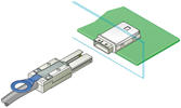 |
| Mini SAS HD | SAS HD | 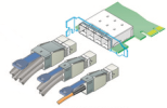 |
| Copper CX4 | CX4 | 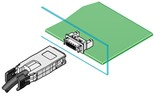 |
| Small Form-factor Pluggable | SFP, SFP+, SFP28 | 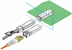 |
| Quad Small Form-factor Pluggable | QSFP, QSFP+, QSFP28 | 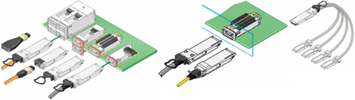 |
PCIe connector types are provided in the PCI Express section.
 Mini SFP
In the second half of 2010, a new variant of the SFP/SFP+ connector was introduced to accommodate the
Fibre Channel backbone with 64-port blades and the planned increased density Ethernet core switches. This new
connector, known as mSFP, mini-SFP or mini-LC SFP, narrows the optical centerline of a conventional SFP/SFP+
connector from 6.25 mm to 5.25 mm. Although this connector looks very much like a standard SFP style connector,
it is narrower and is required for the higher-density devices. The photo at the right shows the difference
between mini-SFP and the standard size.
CXP and CFP
The CXP (copper) and CFP (optical) connectors are expected to be used initially for switch-to-switch connections.
These are expected for Ethernet and may also be used for InfiniBand. CFP connectors currently support 10 lanes of
10 Gbps connections (10x10) that consume approximately 35-40 watts. CFP2 is a single board, smaller version of CFP
that also supports 10x10 but uses less power than CFP. During 2013, quite a bit of development activity is focused
on CFP2. A future CFP4 connector is in the planning stages that is expected to use the 25/28G connectors and support
4x25. CFP4 is expected to handle long range fiber optic distances.
Mini SAS and Mini SAS HD
The Mini SAS connector is the familiar 4-lane connector available on most SAS cables today. The Mini SAS HD connector
provides twice the density as the Mini SAS connector, and is available in 4-lane and 8-lane configurations.
The Mini SAS HD connector is the same connector for passive copper, active copper and optical SAS cables.
The diagrams below compare these two types of SAS connectors.


Source: SCSI Trade Association
PCI Express (PCIe)
PCI Express®, also known as PCIe®, stands for Peripheral Component Interconnect Express and is the computer industry standard for the I/O bus for computers introduced in the last few years. The first version of the PCIe specification, 1.0a, was introduced in 2003. Version 2.0 was introduced in 2007 and version 3.0 was introduced in 2010. These versions are often identified by their generation (“gen 1”, “gen 2”, etc.). It can take a year or two between the time the specification is introduced and general availability of computer systems and devices that use the new version of the PCIe specification.
The PCIe specifications are developed and maintained by the PCI-SIG® (PCI Special Interest Group). PCI Express
and PCIe are registered trademarks of the PCI-SIG.

PCIe 2.0 — Servers that have PCIe 2.0 x8 slots can support two ports of 10GbE or two ports of 16GFC on one adapter.
PCIe 3.0 — On 6 March 2012, the major server vendors announced their next generation servers that support PCIe 3.0, which, among other things, doubles the I/O throughput rate from the previous generation. These servers also provide up to 40 PCIe 3.0 lanes per processor socket, which is also at least double from the previous server generation. Workstation and desktop computer motherboards that support PCIe 3.0 first appeared in late 2011. PCIe 3.0 graphics cards appeared in late 2011. Other types of adapters supporting PCIe 3.0 were announced in 2012 and 2013. The PCIe 3.0 specification was completed in November 2010.
PCIe 3.1 — The PCIe 3.1 specification was released in October 2014. It incorporates M-PCIe and consolidates numerous protocol extensions and functionality for ease of access.
PCIe 4.0 — The PCIe 4.0 specification maintains backward compatibility with previous generations of the PCIe architecture such as PCIe 1.x, 2.x and 3.x. In October 2017, the PCIe 4.0, Version 1.0 specification was released. It may take up to a year or more for products that support the PCIe 4.0 architecture to become generally available.
PCIe 5.0 — The PCI-SIG announced that the PCIe 5.0 specification was completed in May 2019. As with previous generations of the PCIe specification, it may take a year or more before products that support the new specification become generally available to the public. Typically, test equipment that conforms to the new specfication becomes available not long after the specification is complete, followed months later by end-user products.
PCIe 6.0 — In June 2019, PCI-SIG announced that 64 GT/s per lane is the next progression in speed for the PCIe 6.0 architecture. The PCI-SIG estimates that they will complete the PCIe 6.0 specification in 2021.
Data rates for different versions of PCIe are shown in the table below. PCIe data rates are expressed in Gigatransfers per second (GT/s) and are a function of the number of lanes in the connection. The number of lanes is expressed with an “x” before the number of lanes, and is often spoken as “by 1”, “by 4”, etc. PCIe supports full-duplex (traffic in both directions). The data rates shown below are in each direction. Note the explanation of encoding schemes described above.
| GT/s | Encoding | x1 | x2 | x4 | x8 | x16 | |
|---|---|---|---|---|---|---|---|
| PCIe 1.x | 2.5 | 8b/10b | 250 MB/s | 500 MB/s | 1 GB/s | 2 GB/s | 4 GB/s |
| PCIe 2.x | 5 | 8b/10b | 500 MB/s | 1 GB/s | 2 GB/s | 4 GB/s | 8 GB/s |
| PCIe 3.x | 8 | 128b/130b | 1 GB/s | 2 GB/s | 4 GB/s | 8 GB/s | 16 GB/s |
| PCIe 4.x | 16 | 128b/130b | 2 GB/s | 4 GB/s | 8 GB/s | 16 GB/s | 32 GB/s |
| PCIe 5.x | 32 | 128b/130b | 4 GB/s | 8 GB/s | 16 GB/s | 32 GB/s | 64 GB/s |
| PCIe 6.x | 64 | 128b/130b? | 8 GB/s | 16 GB/s | 32 GB/s | 64 GB/s | 128 GB/s |
 M.2 — M.2 is the next generation PCIe connector that can be used for internally mounted devices
such as boot drives in a variety of devices, from mobile to server.
Its multiple socket definitions support WWAN, SSD and other applications. M.2 can support PCIe protocol or SATA
protocol, but not both at the same time on the same device. M.2 supports a variety of board width and length
options. M.2 is available in single-sided modules that can be soldered down, or single-sided and dual-sided
modules used with a connector. M.2 PCIe is also available in a Ball Grid Array (BGA) form factor.
M.2 — M.2 is the next generation PCIe connector that can be used for internally mounted devices
such as boot drives in a variety of devices, from mobile to server.
Its multiple socket definitions support WWAN, SSD and other applications. M.2 can support PCIe protocol or SATA
protocol, but not both at the same time on the same device. M.2 supports a variety of board width and length
options. M.2 is available in single-sided modules that can be soldered down, or single-sided and dual-sided
modules used with a connector. M.2 PCIe is also available in a Ball Grid Array (BGA) form factor.
Mini-PCIe — PCI Express cards are also available in a mini PCIe form factor. This is a special form factor for PCIe that is approximately 30mm x 51mm or 30mm x 26.5mm, designed for laptop and notebook computers, and equivalent to a single-lane (x1) PCIe slot. A variety of devices including WiFi modules, WAN modules, video/audio decoders, SSDs and other devices are available in this form factor.
U.2 — U.2 (formerly SFF-8639) is the I/O backplane connector designed for high-density SSD storage devices and is backward compatible with existing storage interfaces. SFF-8639 supports PCIe/NVMe, SAS and SATA devices and enables hot plug and hot swap of devices while the system is running.

U.3 — U.3 is the common name for a new type of backplane connector that conforms with the SFF-TA-1001 specification. SFF-TA-1001 Rev. 1.0 was ratified in November 2017 and Rev. 1.1 was ratified in May 2018. The U.3 standard defines a common bay type and connector for SAS, SATA, and NVMe devices enabling single, dual, and wide-port SAS, SATA, and x1, x2 or x4 NVMe devices to all work on the same shared signals and connectors. U.3 is backward compatible with U.2, also known as SFF-8639. With U.3, the locations of the SAS devices and NVMe devices are now in the same physical location, allowing NVMe SSDs to leverage the same backplane infrastructure as SAS and SATA devices and reducing the cost to produce such a backplane. It is expected that backplanes supporting the U.3 specification will allow NVMe, SAS and SATA devices to be intermixed in the backplane, rather than having separate drive bays for NVMe SSDs. U.3 backplanes are expected to appear in servers and other compute platforms possibly by late 2019.

M-PCIe™ — M-PCIe is the specification that maps PCIe over the MIPI® Alliance M-PHY® technology used in low-power mobile and handheld devices. M-PCIe is optimized for RFI/EMI requirements and supports M-PHY gears 1, 2 and 3 and will be extended to support gear 4.
I/O Virtualization (SR-IOV & MR-IOV) — In 2008, the PCI-SIG announced the completion of its I/O Virtualization (IOV) suite of specifications including single-root IOV (SR-IOV) and multi-root IOV (MR-IOV).
- SR-IOV enables a PCIe device to support multiple Virtual Functions and is currently used with several 10GbE and faster NICs and with various hypervisors.
- MR-IOV enables multiple non-coherent Root Complexes (RCs) to enhance resource utilization of PCI hardware and is primarily the overlaying of multiple Virtual Hierarchies (VHs) over a shared physical set of multi-root aware (MRA) and non-MRA components.
PCIe External Cables —The concept of sharing PCIe devices or providing access to PCIe devices that may be physically larger than some smaller form-factor systems can accommodate has led to the development of external connections to some PCIe devices. Cables have been developed for extending the PCIe bus outside of the chassis holding the PCIe slots. These cables are specified by indicating the number of PCIe lanes (x4, x8, etc.) supported. Cables are typically available for x4, x8 and x16 lane configurations. Common cable lengths are 1m and 3m. The photo below shows some PCIe cables and connectors. PCIe can also be carried over fiber-optic cables for longer distances. In the future we will begin to see the shift from PCIe cables and connectors to OCuLink cables and connectors, also shown in the image below.
OCuLink — OCuLink is intended to be a low-cost, small cable form factor for PCIe internal and external devices such as storage devices or graphics adapters, offering bit rates starting at 8 Gbps, with headroom to scale, and new independent cable clock integration. OCuLink supports x1, x2 and x4 lanes of PCIe 3.0 connectivity. OCuLink supports passive cables capable of reaching up to 2—3 meters and active copper and optical cables. Active copper cables can reach up to 3—10 meters while active optical cables can reach up to 300 meters in length. The OCuLink specification Revision 1.0 was published in October 2015 and is available to PCI-SIG members via the online specification library.

The original version of this page is available at www.demartek.com/Demartek_Interface_Comparison.html on the Demartek website.